IC-40 into Easy Touch

CatalanBull

Bronze Supporter
Apr 3, 2025
18
Corona, CA
Pool Size
13500
Surface
Plaster
Chlorine
Salt Water Generator
SWG Type
Pentair Intellichlor IC-40
Hi,

I recently wanted to get take care of my own pool, someone recommended TFP and I have to say I’m so happy and so greatful for this. After having an IC-40 salt generator installed getting the TFP 100 Kit with the C-600 and smart stir. I analyzed the water several times, the CYA was around 140 so I had to replace about 85% of the water. Right now the numbers are looking really good, trying to get the PH down but I think that'll be a never-ending battle. Thanks for all the information and knowledge.

The IC-40 is working well, but unfortunately the installer (who was recommended by Pentair) didn’t connect it to my Easy Touch. He said I didn’t tell him to do it :cautious: and he wants to charge me $175 to connect it. I have been looking and it appeared to be a fairly easy job, just need to connect 4 colored wires from the power center to the Easy Touch. However, as I was looking into it, I realized there appears to be a circuit breaker for the IntelChlor that I’m missing. I’m contemplating at 3 options:

1. Pay him the $175 to do it.
2. Is the circuit breaker necessary? Because the terminals where the wires would go into the ET already have wires in, so there’s already power there.
3. Since the IC-40 and the power center already has power and it’s up and running, can I just connect the yellow and green wire where they go and leave the others connected as they are? If so, do I need to remove the green wire that is connected at the moment?
4. Any other option I can’t think of?

The motherboard:
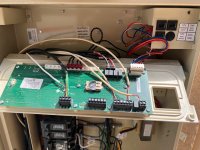
IMG_3288.jpeg

The IC-40 Power Center as it is set up right now:
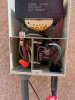
IMG_3290.jpeg

The inside of the Easy Touch with indications of where the wires from the IC-40 Power Center are connected to right now: (the wires come in thru the second slot left to right at the front).
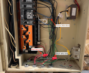
Screenshot 2025-04-14 at 1.12.55 PM.png

Thanks!
Roger
 
Last edited:
You only have the SWG CB in the EAsyTouch when you have the Power Cenetr integrated in the EasyTouch cabinet. Since you have the standalone Power Center you do not have the SWG CB.

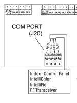
All you need to do is connect two wires - yellow and green - from the Power Center RS-485 connector to the Easy Touch RS-485 connector.

You can put two wires under one screw on the RS-485 connector and it looks like you already have two wires connected.

You can make a "pigtail" cable to connect to the com port, and connect as many devices as you like to the pigtail. In other words, one com port can handle all your devices wired in parallel. That works for many folks but some have RS-485 comm problems.

Pentair 520818 COM Port Expansion Module adds additiuponal RS-485 Comm connector to your system...


  • Like
Reactions: CatalanBull
You only have the SWG CB in the EAsyTouch when you have the Power Cenetr integrated in the EasyTouch cabinet. Since you have the standalone Power Center you do not have the SWG CB.

All you need to do is connect two wires - yellow and green - from the Power Center RS-485 connector to the Easy Touch RS-485 connector.

You can put two wires under one screw on the RS-485 connector and it looks like you already have two wires connected.

You can make a "pigtail" cable to connect to the com port, and connect as many devices as you like to the pigtail. In other words, one com port can handle all your devices wired in parallel. That works for many folks but some have RS-485 comm problems.

Pentair 520818 COM Port Expansion Module adds additiuponal RS-485 Comm connector to your system...


Thank you Allen! I'll try that tomorrow when I get the wires. And I can leave the current green wire that goes from the left side of the power center as it is, I can assume?

Thanks,
Roger
 
Roger,

Please show us a pic or two of your relays... I specifically need to see the one in the upper left, the Pump/Filter relay..

Thanks,

Jim R.
Thanks Jim, I'm attaching the pictures here. I think these are the relays, sorry I'm not very versed in electronics! :)

Roger
 

Attachments

  • IMG_3298.jpeg
    IMG_3298.jpeg
    351.6 KB · Views: 5
  • IMG_3299.jpeg
    IMG_3299.jpeg
    332.7 KB · Views: 5
Thank you Allen! I'll try that tomorrow when I get the wires. And I can leave the current green wire that goes from the left side of the power center as it is, I can assume?

Thanks,
Roger
Do not mix low voltage comm wires with high voltage wires.

I am not sure what green wire you are referring to but I believe it is the green ground wire.
 
  • Like
Reactions: CatalanBull
Roger,

Thanks for the pics, but I was not able to see what I wanted to see... :(

I would like you to run a couple of quick tests for me...

1. Put the system into the Service mode... the pump will stop, do NOT press the "F" button, leave the pump off..

2. Does your pump still have power to the display? If it is an IntelliFlo, does the display show an RPM screen or is it blank?

3. Are there any lights on your IC40?? There should be no lights in the Service mode.

4. Put the system back into Auto.. It may take five minutes for things to restart...

Thanks,

Jim R
Thanks Jim,

I did that, the pump (IntelliFlo) screen is blank (no power) and no lights to the IC40.

Roger
 

Enjoying this content?

Support TFP with a donation.

Give Support
That is the ground wire.

You need to run the low voltage comm wires up the left side raceway. Do not run them through the high voltage area.
Thank you, so to summarize:

1 - I connect the yellow and green wire to the slots 2 and 3 in the power center. Then channel them thru one of the knockouts from the underside.
Screenshot 2025-04-14 at 5.03.26 PM.png
2 - Get those two wires in the Easy Touch and route them to the top. Connect them to the slots 2 and 3 of the J20 terminal.Screenshot 2025-04-14 at 5.04.25 PM.png

3. Leave the thick black, green and red wires that go from the other side of the power center to the Easy Touch as they are.

Does it sound right?

Thank you again!

Roger
 
Thank you, so to summarize:

1 - I connect the yellow and green wire to the slots 2 and 3 in the power center. Then channel them thru one of the knockouts from the underside.
View attachment 638098
2 - Get those two wires in the Easy Touch and route them to the top. Connect them to the slots 2 and 3 of the J20 terminal.View attachment 638099

3. Leave the thick black, green and red wires that go from the other side of the power center to the Easy Touch as they are.

Does it sound right?

Thank you again!

Roger
Yup. You got it. Except you already have two wires in J20. So you have to create a pigtail with a wirenut.

Then you need to enable the IntelliChlor in the EasyTouch. @Jimrahbe can tell you where to find that in the menus.
 
  • Like
Reactions: CatalanBull
I did that, the pump (IntelliFlo) screen is blank (no power) and no lights to the IC40.
Roger,

That is good for the IC40, it means the AC power to the IC40's external Power Center is connected to the load side of the Pump/Filter relay.. That is how it should be..

Bad when it comes to the pump.. When you go into the Service mode, you should be able to use the controls on the pump's display.. The fact that the display is blank, means that the AC to the Pump is being controled by the Pump/Filter relay.. This is just flat out wrong. The Pump should get constant AC power...

To fix the pump issue.. simply move the wires that power the pump from the Load side pins to the Line side pins.. This will send constant AC to the pump. This would leave the load side controlling just the SWCG..

Thanks,

Jim R.
 
  • Like
Reactions: CatalanBull
To fix the pump issue.. simply move the wires that power the pump from the Load side pins to the Line side pins.. This will send constant AC to the pump. This would leave the load side controlling just the SWCG..
Jim, it looks to me like the installer tapped into the pump power wires at the bottom of the cabinet and wire nutted the Intellichlor power to them.

If I am correct then when the pump power wires are moved to the LINE side it will also give continuous power to the SWG which is not desired.

The pump power wires need to be connected to the LINE side of the filter pump relay while the SWG power center needs to be connected to the LOAD side of the filter pump relay.

The cuts and wire nuts connecting the wires all need to be fixed.

1744678286739.png
 
Last edited:
  • Like
Reactions: CatalanBull
Roger,

Allen sees your wiring differently than I do, so it would be best if you rewired things so the the IC40 Power Center gets its AC power from the load side of the pump filter relay.. and that the pump gets constant AC power..

Since I am now unsure which wires go where, it would be best that you follow each wire to and from the Pump filter relay and rewire as necessary.

If you can't do that, then at least tell me where the the wires on the load side of the pump/filter relay go...

Thanks,

Jim R.
 
  • Like
Reactions: CatalanBull
Thank you Jim. The pump wires come in thru the 3rd slot at the bottom (3rd from the left). There’s 2 red wires and one green wire coming out of there. One of the red wires is nutted with a black wire that goes to the IC40 Power Center and with another black wire that goes up to the load 2 terminal of the filter/pump relay. The other red wire is nutted with another red wire that goes to the IC40 Power Center and with a black wire that goes to the load 1 terminal of the filter/pump relay. The greeen wire goes to a ground bus at the center.

In the wiring diagram on the cover of the box I see the relay has four terminals: line 1, load 1, line 2, load 2. I hope everything I said makes sense.

So if I understand correctly I should move the pump black wires to line 1 and 2, and keep the black and red wires of the IC-40 to the load size as they’re now, correct? This sounds a bit challenging for me because the wires from the IC40 Power Center were cut just right for those nuts and won’t reach the relays. Is that something that needs to be done or is good enough to work as it is? If I have to do it I’ll see if I can get some help or an electrician to fix it because it’s above my electrical skills.

Wiring the green and yellow to the J20 on top should be easy, but this is a bit more challenging.

Thank you again!
Roger
 

Attachments

  • IMG_3319.jpeg
    IMG_3319.jpeg
    704.9 KB · Views: 2
Thank you Jim, tomorrow I’ll talk to my father-in-law who is a retired electrical engineer and see if he feels comfortable doing it. Basically what needs to happen is:

1. Move the pump black wires from load 1 and 2 to line 1 and 2
2. Keep (by rewiring) the black and red wires of the IC-40 to the load size as they’re now.

That should do it, correct?

Thank you so much!
Roger
 

Enjoying this content?

Support TFP with a donation.

Give Support