Mar 4, 2018
6
Birmingham
Pool Size
25000
Surface
Vinyl
Chlorine
Salt Water Generator
SWG Type
Hayward Aqua Rite Pro (T-15)
Hey pool friends -

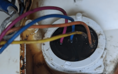
Hayward Aqua Plus automation system with a T-CELL-15 that finally rusted on me and is leaking; I'm looking at wiring diagrams, troubleshooting guides and pictures online; all my research for the T-CELL-15 tells me the yellow and orange wires (going to the temp sensor) are not used. Most pictures I've come across show them cut off, yet mine seem to be intact and part of the sensor.

Can anyone tell me what these do?
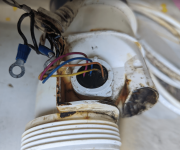
1657640004423.png


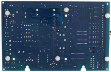
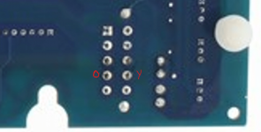
I ask because, in my efforts to get a replacement, I tried a generic cell that only has the 6 wires in the molex (pictured below), but I immediately get a 'sensor fault' error when the chlorinator turns on; this makes me believe all 8 wires are required. Is this just for the automation systems maybe?


Generic Cell Molex (only 6 connectors)
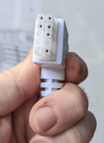
Generic cell molex


OEM/Original Hayward Molex (has 10 connectors for all 8 wires)
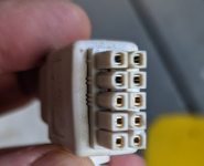
1657640334413.png


Thanks in advance for any info anyone can provide.
 
Last edited:
Thanks @mknauss - that was one of the first threads I came across. Most everything I have read references this same info telling me that they are not used, but wasn't sure if maybe that was for a stand-alone system (Aqua-Rite versus Aqua-Plus) and maybe somehow the Aqua-Plus systems required these extra two wires.
  • 1) Black - Power to cell
  • 2) White - Power to cell
  • 3) Black - Power to cell
  • 4) White - Power to cell
  • 5) Brown - Not used
  • 6) Red - Goes to thermistor
  • 7) Orange - Not used
  • 8) Yellow - Not used
  • 9) Green - Not used
  • 10) Blue - Goes to thermistor.

So maybe they are just terminated into the black waterproofing putty and are not connected to anything.
1657646349475.png

I was thinking maybe Hayward had these two wires hooked up some way to prevent people from using a generic salt cell replacement; sort of like a check for continuity at the controller that, if not present, would turn the cell off.

Guess I can dig that waterproofing out and see.
 
Last edited:
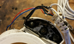
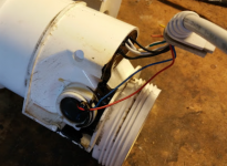
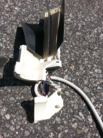
If anyone is familiar with Phillip Doolittle's post mortem of his salt cell - he shows the yellow, orange, green and brown all being cut off (from the factory) right as they exit the harness so clearly it seems there might be different scenarios where Hayward used them for some and not others.

(again, not my pictures, just some reference pics from another user that was doing a post-mortem on his salt cell after failure)
1657650975647.png1657651063498.png


Inyopools has a generic cell that states direct replacement with Hayward T-CELL-15 but then has the disclaimer that they aren't supported on automation systems, so this leads me to believe there is something specific about the automation systems that need these two wires?

1657651905298.png
 

Attachments

  • 1657651879027.png
    1657651879027.png
    13.4 KB · Views: 9
Last edited:
The old cell only used the red and blue.

Some newer cells use the orange and yellow, but I am not sure why.

Probably an attempt to prevent the use of third party cells.

Cut the yellow and orange going to the cell and measure the resistance.

The generic cells will work on the older circuit boards, but the newest circuit board is looking for a specific reading from the yellow and orange.

The Hayward T-Cell uses 13 plates (blades). The 2 white wires go to the center plate and one black wire goes to each outer plate.

1657652952496.png
 
Cut the yellow and orange going to the cell and measure the resistance.

It might be continuity, or maybe a second thermistor or maybe some sort of RFID tag with a serial number for original cells.

I'm not even sure that it's legal for them to try to prevent aftermarket cells from being used.

A manufacturer cannot create "Tie-In Sales" Provisions.

Generally, tie-in sales provisions aren’t allowed.

These are provisions that state or imply that a consumer must buy or use an item or service from a particular company to keep their warranty coverage.

No warrantor of a consumer product may condition his written or implied warranty of such product on the consumer’s using, in connection with such product, any article or service (other than article or service provided without charge under the terms of the warranty) which is identified by brand, trade, or corporate name

Still, if it turns out that the aftermarket or recycled part was itself defective or wasn't installed correctly, and it causes damage to another part that is covered under the warranty, the manufacturer or dealer has the right to deny coverage for that part and charge you for any repairs.

The FTC says the manufacturer or dealer must show that the aftermarket or recycled part caused the need for repairs before denying warranty coverage.


Last edited:
that was the first thing that came to mind - some sort of serial number (y)

I checked for continuity (none) and never got a solid number for ohms (kept auto-ranging at around 5-6MΩ) so doesn't seem as if a second thermistor is in play there.

For giggles, I tested the blue and red and got a steady 9940 ohms so ohmmeter is working (it's about 78 degrees where I'm testing and assuming 10k thermistor).
 

Enjoying this content?

Support TFP with a donation.

Give Support
I checked for continuity (none) and never got a solid number for ohms (kept auto-ranging at around 5-6MΩ) so doesn't seem as if a second thermistor is in play there.
Can you cut it open and see what's inside?

Try not to damage it as you might be able to wire it to your board to make the board think that it has a good cell.
 
Try not to damage it as you might be able to wire it to your board to make the board think that it has a good cell.
This is exactly what I was thinking about trying; let me give it a whirl and I'll post back here if/when I get a new generic cell to test with ... I sent the other back immediately thinking it wouldn't be useable.

Thanks for all the ideas - this has been helpful!
 
  • Like
Reactions: JamesW
T-15 cell plug pinout. My 6 month old cell was causing a false "HOT" reading. I took apart an old one and made this drawing of the pinout of the plug. My sensor was reading about 2000Ω at 80° F. This is way too low and should be closer to 8000Ω. I will remove the old sensor and pot in a new one to save the cell.
 

Attachments

  • HAYWARD T - CELL 15 PINOUT.pdf
    10.6 KB · Views: 17
Last edited:
Hey pool friends -

Hayward Aqua Plus automation system with a T-CELL-15 that finally rusted on me and is leaking; I'm looking at wiring diagrams, troubleshooting guides and pictures online; all my research for the T-CELL-15 tells me the yellow and orange wires (going to the temp sensor) are not used. Most pictures I've come across show them cut off, yet mine seem to be intact and part of the sensor.

Can anyone tell me what these do?

View attachment 434973


I ask because, in my efforts to get a replacement, I tried a generic cell that only has the 6 wires in the molex (pictured below), but I immediately get a 'sensor fault' error when the chlorinator turns on; this makes me believe all 8 wires are required. Is this just for the automation systems maybe?


Generic Cell Molex (only 6 connectors)
View attachment 434974


OEM/Original Hayward Molex (has 10 connectors for all 8 wires)
View attachment 434975


Thanks in advance for any info anyone can provide.
I have made a pinout drawing of the connector
 

Attachments

  • HAYWARD T - CELL 15 PINOUT.pdf
    10.6 KB · Views: 9
  • HAYWARD T - CELL 15 PINOUT.jpg
    HAYWARD T - CELL 15 PINOUT.jpg
    126.5 KB · Views: 12
Thread Status
Hello , This thread has been inactive for over 60 days. New postings here are unlikely to be seen or responded to by other members. For better visibility, consider Starting A New Thread.