Brand New Max e Therm burning through igniters literally

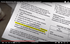
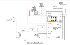
Note that the Mastertemp does not use a separate flame sense rod because it uses the HSI (Hot Surface Ignitor) as the Flame Sense Rod, but it is the same principle.

The Unit uses a DPDT relay to control voltage to the HSI (Hot Surface Ignitor).

When not in ignitor heating mode, the voltage goes only to S2-FS.

You can't have the other line connected or you will get heating of the HSI.

1740708706989.png
 
Last edited:
For a separate flame sense rod, you can test for DC microamps in series, but you cannot do this with the HSI because the amperage will be about 4 amps during HSI Heating.

This is why the Fenwal provides a dedicated Flame Sense testing location with a + and - pin to test.
 
Last edited:
  • Like
Reactions: setsailsoon
The same electrode that lights the flame can also act as the flame sensor in a system known as "Local Sense."

"Remote Sense" uses a separate sensing rod positioned at an optimal location in the combustion chamber relative to the burner.

Another important consideration is that HSI elements are poor flame sensors when compared to electrodes.

Many engineers who design HSI into their product will use a separate flame sense rod to monitor the flame.

The result is a reliable system, but there is the added cost, wiring and installation of another component in addition to the more expensive hot surface igniter.

 
1740713832757.png
1740713750413.png

Flame Fault
If at any time the main valve fails to close completely and maintains a flame, the flame sense circuit will detect it and energize the inducer blower.

Should the main valve later close completely removing the flame signal, the inducer blower will be turned off following the optional post purge period.

Flame Current Measurement.

Flame current is the current that passes through the flame from sensor to ground.

To measure flame current, connect a True RMS or analog DC micro-ammeter to the FC+ and FC- terminals.

Readings should be 1.0 µA DC or higher.

If the meter reads negative or below "0" on scale, meter leads are reversed.

Reconnect leads with proper polarity.

Alternately, a Digital Voltmeter may be used to measure DC voltage between FC+ and FC- terminals.

Each micro-amp of flame current produces 1.0 VDC.

For example, 2.6 VDC equates to 2.6 µA.

A good burner ground that matches the control ground is critical for reliable flame sensing.

1740714092393.png


Note: During a fault condition, the LED will flash on for 1/4 second and off for 1/4 second as needed to indicate the fault code.

The code will repeat every 3 seconds.

Removing power from the control will clear the fault code.


Attachments

  • series-35-66_24-VAC-hot-surface-ignition-control-F-35-66.pdf
    799.3 KB · Views: 0
Great info here. I have a new this year Max-e-therm heater. No igniter issues yet but if I do have this issue I'll check the insulation. Only problem I had initially is the electrician's helper hooked it to 110v instead of 240. Didn't seem to hurt anything. The fact the fan was running slow also was a giveaway.
 
1740719359919.png

For a rectified system, when an AC supply voltage is placed across the two electrodes during the first half of the AC cycle, the flame rod is positive and the grounding area is negative (Figure 9 A).

The positively charged ions collect on the negative charged grounding area.

Since the grounding area is very large, it holds many ions.

The positively charged ions pull a high stream of electrons into the flame, more than if the grounding area was the same size as the flame rod.

This results in a high current flowing from the grounding area to the flame rod during the first half cycle of the AC supply voltage (Figure 9 C).

During the second half cycle, the reverse process takes place (Figure9 B).

However, the capacity of the flame rod to hold ions is less than the grounding area and the resulting flame current is smaller (Figure 9C).

Since the current in one direction is so much larger than the current in the other direction, the resultant current is, effectively, a pulsating direct current (Figure 9C).

The flame signal should be steady when measured with a DC microammeter (μA).


The Process of Flame Rectification

The board puts out 40VAC to 120VAC (manufacturer dependent) on the flame rod wire.

The flame rod is always energized when the furnace board is powered.

Honeywell Smartvalves are ~170 to 180VAC.

Honeywell S8610U3009 are ~170VAC that will produce ~1 to 2 µADC.

The fuel ignites and flame is present.

The 40VAC to 120VAC passes current through the flame to complete the circuit by grounding to the burners

This "grounding" of the circuit makes a good ground essential!

The ions in the flame only allow half (+ ions) of the AC sine wave to pass through the flame.

This is called "Rectification".

This process is the changing of the AC signal into a rectified DC signal.

Once the flame is present and this rectification circuit completes, then power flows through the circuit and is measured in Microamps DC (µADC).

The furnace board will constantly monitor this µADC signal to verify a safe operation during the heating run cycle.

A typical flame rod circuit will carry between 1 to 6 µADC

Most furnace boards need a minimum of 0.5 µADC for the furnace to stay running.

 
As for the 3.4 volts I was seeing at the ignitor when the heater is powered off/idle, but still electrically hot at the breaker, he indicated this is normal behavior but couldn’t provide a definitive answer as to why. He did indicate it has nothing to do with flame sensing when I asked him directly if that’s what it may be.
You can't check S1 to S2, you have to test from S2 to ground.

Most likely, the voltage will be about 100 volts.

It is for Flame Sensing.

The DPDT relay is on Flame Sense when the relay is not powered.

Flame sense is S2 to 100 volts AC and S1 is not connected to anything.

When the relay coil is powered, S1 connects to Hot (120 volts) and S2 connects to neutral.
 
HSI checkout

Check cold resistance
HSI manufactured by Coorstek (KIT03033 pre Sept 2021) resistance range = 40-80Ω @ 75°F
HSI manufactured by SCP (KIT03033USA Sept 2021-current) resistance range = 65-120Ω @ 75°F
Check amperage of HSI when energized
HSI manufactured by Coorstek (KIT03033 pre Sept 2021) range = 3.5 - 3.9A @ 132vac
HSI manufactured by SCP (KIT03033USA Sept 2021-current) range = 3.3 - 3.7A @ 116vac.

1740721378540.png


At the end, with 120Vac it get a bright light in 1 sec with a current of ~3.9Aac. I keep it ON during 3 secs.
 
Last edited:
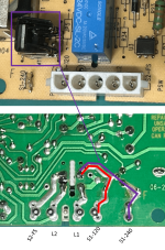
The DPDT relay has Normally closed contacts from S1 and S2-FS (Red Dots) to the Flame Sense Voltage Terminals (Blue Dots).

S2-FS should have 90 volts to ground all the time (except when the ignitor is energized) to detect a Flame when no call for heat.

The Top Blue Dot is connected to S1, but the top blue dot is a dead terminal.

The bottom Blue Dot has 90 volts AC connected to S2-FS, which sends voltage to the HSI (Hot Surface Ignitor).

The voltage will go to S1 through the HSI (Hot Surface Ignitor)(Orange Line), but there will be no current because the top blue dot is not connected to a ground or neutral.

So, if you measure from S1 to Ground or S2 to ground, you should get 90 volts AC.

If you measure from S1 to S2, you should get 0 volts.

During the 20 second ignitor heatup, S1 connects to 120 volt line power and S2 connects to Line Neutral and the HSI should use 3.9 amps (450 watts).

Then the relay switches back to Flame Sense mode.

1740792175316.png

1740791263257.png
1740790711063.png
1740790686619.png
 

Enjoying this content?

Support TFP with a donation.

Give Support
I suspect that the 90 volt AC Flame Sense power is probably designed to be very weak.

If you were to connect the S1 to ground or neutral (Completing the circuit through the Hot Surface Ignitor), I suspect that the voltage would probably mostly drop out and not sustain any significant current.

Even under a 5 microamp load, the voltage drops down a lot.

1740795750646.png
 
Last edited:
James,

The deep dive you do every now and then on a broad array of technical issues from circuit design to fluid mechanics to water chemistry (and @JoyfulNoise adds a lot of content there also) is amazing. Thanks for all both of you do on both topics. It has been incredibly helpful to me in finishing up my pool with some DIY controls and well water issues. I'll update what I've done in the appropriate threads later today.

Chris
 
  • Like
Reactions: JamesW
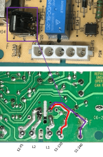
The purple dots are the 24 VDC coil.

When the power input is 240 volts, the ignitor is powered by S1/240 and S2/FS instead of S1/120 and S2/FS.

This is changed by the voltage selector plug (Red or Black).

The Voltage Selector Plug also changes the Blower Windings from Series (For 240 Volts) to Parallel (For 120 Volts).

The Voltage Selector Plug also changes the System Transformer Windings from Series (For 240 Volts) to Parallel (For 120 Volts).

1740841321690.png

Manufacturer: SANYOU

Manufacturer part number: SMI-S-224L

Type of relay: electromagnetic

Contacts configuration: DPDT

Rated coil voltage: 24V DC

Contact current max: 8A

1740841952984.png

1740841964076.png

1740842128709.png

When the heater is operating (connected to) in 240Vac, the IC MT1 (in purple box) is switching the input L1 to get 120Vrms in the ignitor. The picture diagram shows the L1 circuit route: a) red (110V direct) and b) purple (240V switching by MT1).

1740842720086.png
1740851236638.png
 

Attachments

  • 1740842158108.png
    1740842158108.png
    591 KB · Views: 0
Last edited:
  • Like
Reactions: Hulaomr
1740843779712.png
1740843690263-png.630216


1740843933976.png
1740844048827.png
1740848842283.png
 

Attachments

  • 1740843690263.png
    1740843690263.png
    207.7 KB · Views: 9
  • 1740843715159.png
    1740843715159.png
    591 KB · Views: 0
Last edited: