- Jul 24, 2017
- 168
- Pool Size
- 8400
- Surface
- Plaster
- Chlorine
- Salt Water Generator
- SWG Type
- Pentair Intellichlor IC-40

This is going slow because one of our parents fell and broke a hip last week so a lot of our discretionary time goes there. But I just made time to cut power, decouple the IntellipH from the Easy Touch, and then run the IC-40 power cord directly into that port on the Easy Touch. Started everything up and was surprised to see not even a flicker from the two week old IC-40. I have not had time to disassemble the IntellipH yet to check for burned leads, and I will still do that next, but I'm not sure I should expect to find the burnt pin problem since most of you that have had that problem came through it with undamaged IC cells. Back over to the hospital for now.The main things to be aware of ...
Does this mean that it is working or not working?Started everything up and was surprised to see not even a flicker from the two week old IC-40.
Sorry -- no lights, no nothing, not even a flicker. Not working.Does this mean that it is working or not working?
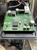
Thanks James. I see the leads I need to check, thanks for making that so clear. I found that DC connector in the upstairs (low voltage side) of the Intellitouch housing. This goes beyond what I ordinarily do so I should ask a couple of basic questions. Do I unplug that white connector from the board so that I can place the test tips in from that direction? Also, this is ridiculously basic but I should ask anyways -- which test tip goes where when I'm testing the voltage on the black wire, and which test tip goes where when I'm testing the voltage on the red wire?You should get 39 volts DC at red and black.
This would sort of fit my situation too -- twelve year old power supply had spent nearly that entire time with an IC-20 asking for power. Then all of a sudden along comes an IC-40 asking for significantly more. The old power supply hangs in there for a week or two and then says goodbye.Check the voltage coming from the power supply.
Okay got it. So just placing the red lead into that socket the meter reading bounced around between 4 and 8 volts. When I set it to just read give me the High reading it did the same and then spiked up to the mid 20's and then to 34. Testing the black lead the same way produced similar single digit values. When I set it to display only the high it finally gave me a reading in the mid 20's. I have not simultaneously placed the black (first) and then the red to test both simultaneously but can do that next if that's really what we're after.The red lead goes to the red wire and the black lead goes to the black wire, but it will work either way.
If you reverse the leads, it will just read negative voltage.
You should be able to poke the leads into the gaps where the wires go into the plug.
That took all the bouncing around away. Steady and stable at 43.4 volts.Yes, test red to black on DC voltage.

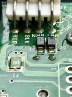
James, thanks for the help and patience. I think we're talking about the 4 female leads built into the female "screwable" portion of the cable, shown here by my arrow? Gotta confess that I have no idea which of those 4 little receiving sockets I need to test with the black test tip and the red test tip to determine whether the cable is delivering the available power?Since you are getting good voltage, it points to a bad cell or maybe a bad cable.
You can measure for voltage in the holes of the female cable where the cell plugs in.

I think I'm right with you. The IntellipH box is running and behaving as usual. This seems to suggest the cabling in service all the way down to it is working fine. When I know how to do it, what I need to test is the equivalent socket (shown by my arrow) that's outputting from the IntellipH, where the IC usually screws in, to see if THAT plug is still delivering power. If it is, whether it's the new IC cell or the cable that came with it, one of those two has to be the problem.Since you are getting good voltage, it points to a bad cell or maybe a bad cable.
You can measure for voltage in the holes of the female cable where the cell plugs in.