Wiring help - No neutral wires on breakers

OolDad

Member
Oct 28, 2022
24
Orlando, FL
Surface
Plaster
Chlorine
Liquid Chlorine
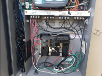
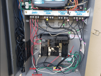
After a power surge did a lot of damage, I discovered I don't have a GFCI breaker for my pool lights. I've got to replace the regular QP type breaker with a GFCI breaker, but I'm a little confused by the wiring here (see pic).

Questions:

A) What's up with the neutral wiring? Does this look normal? Can I just
(1) pop in the appropriate new GFCI breaker,​
(2) attach the connected GFCI neutral-out to the neutral bus,​
(3) attach the black wire from the old breaker that leads to the Lights Relay to the new GFCI breaker, and​
Most importantly: I assume I should also (4) move the load's neutral wire (from Aux 1/Spa Light wire bundle) from the neutral bus to the GFCI neutral-in? Is that right? (I don't see a neutral wire for the main pool light, just the load out wire to the junction box.)​


B) Doing all that may leave two neutrals in that path, one from the automation board to the neutral bus and one connected in to the GFCI from the load on Aux 1 (Spa Light) and then out of the GFCI to the neutral bus. It's probably not ok to leave it like that, right? There's a jump wire from the Lights relay to Aux 1, then automation.
Should I change the wiring to
(1) two separate lines in from a 2-pole GFCI for each of the two lights (with no jump wire from Lights to Aux 1) and a third line directly from a separate regular breaker to the automation, or​
(2) just keep the two lights on a one-pole GFCI using the current wiring as is with the existing jump wire from the Lights relay to the Aux 1 relay, but move the automation board line-in wire directly to a regular breaker (not connected to Aux 1)?​


C) Anything else jump out at you that needs attention - aside from cleaning up the sloppy/exposed contacts on the relays? Maybe I should swap out the stranded wire for solid copper wherever possible. Probably should change the pump/heater/blower breaker to GFCI too, but no idea what to make of no neutrals at all on the load there.
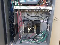


20221026_133422.jpg
 

Attachments

  • 20221026_133429.jpg
    20221026_133429.jpg
    582.6 KB · Views: 48
  • 20221019_152419.jpg
    20221019_152419.jpg
    359.9 KB · Views: 49
Dad,

Does the 120 VAC run directly from your automation to the lights in the pool? Or, does the power run to a transformer box and then to the pool?

Back up a little and show us what is around the automation box.

Thanks,

Jim R.
 
  • Like
Reactions: OolDad
The cord with the red dot looks like the light cord (red arrow).

That looks like it goes to AUX 1 where it says B with and arrow.

The "Lights" relay looks like it goes to something else that works on 120 volts.

Are the pool and spa lights on separate controls or do they turn on and off at the same time??

Do you have any transformers or junction boxes for the lights?

The AUX 2 relay looks like it goes to a 240 volt piece of equipment (Maybe the blower).

Can you show the whole system?

What heater do you have?

Where is the heater power coming from?

You probably need to have an electrician go over everything and make sure it is up to code.

The system looks like it is about 16 years old (Maybe from about 2006).

How old is everything?

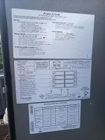
Can you show the door label?

1667349534008.png
 
Last edited:
  • Like
Reactions: OolDad
Filter pump and Blower AUX2 is fed by 240V CB.

Light1, Light2, and panel is fed by 120V CB. There is a neutral from the lights and from the panel.

It is not clear to me where the heater is powered from.

Current NEC requires GFCI CB for pumps, gas heaters, and 120V lights. Assumption is you don;t have 12V LED lights.

GFCI CB neutral pigtail gets connected to neutral bus.

All neutrals from the devices powered from a GFCI CB must connect back to the neutral connection on the CB and not the neutral bus. So the neutral from the light and from the panel should be wire nutted together with a white pigtail that connects to the 120V GFCI CB neutral screw.

240V equipment have two hot lines black/red and no white neutral line.

Is all the wire in the Load Center 12 gauge?

There is no reason to replace stranded wire with solid wire if it is the proper gauge.


panel.png
 
  • Like
Reactions: OolDad
The "Lights" relay might go to a light, but where is the neutral for that?

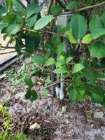
Look for a pool light junction box around the pool or under the diving board.

My guess is the two light wires (hot, neutral, ground) run into the junction box. The two neutrals from the lights are connected to one neutral line and the ground wires from both lights are connected to a ground wire. Then the common neutral line, common ground line, and hot wires for both lights run to the Load Center from the junction box.

img_0779-002-jpg.79229
 
  • Like
Reactions: OolDad
Looks pretty sketchy to me.

Definitely need more data.

I recommend that an electrician be consulted for an evaluation and remediation plan to make everything code compliant and safe.
 
  • Like
Reactions: OolDad
It appears the neutral conductor for the lights is connected to the 3 screw from the bottom on the neutral buss bar.
The top right beaker services the lights and the controller. Replace it with a single pole GFIC breaker.
The neutral on the GFIC breaker will connect to the neutral buss bar.
The neutral for the lights and the controller (top wire on the neutral buss bar) will have to be wired nutted together with a pig tail and the pigtail connected to the new breaker. You can not place more than one wire on the terminal of a breaker. Personally I like the WACO wiring blocks better than wire nuts.
 
  • Like
Reactions: OolDad
Since you have open breaker slots I would add a 120V 20A GFCI CB and move the lights to that breaker.

Move the green dot hot wire on my pic above that powers the controller to go directly into the existing 120V CB.

That keeps your controller on a separate CB from your lights.

Should your lights trip the GFCI your controller will not go down. Otherwise having a GFCI problem with your lights can shutdown the controller and your entire pool.
 

Enjoying this content?

Support TFP with a donation.

Give Support
Does the 120 VAC run directly from your automation to the lights in the pool? Or, does the power run to a transformer box and then to the pool?
There's no transformer, it's 120v at the pool. Wiring does go to a junction box first.

I removed some info before posting because I was making it too complicated. Mostly concerned about the neutral wiring. Thought it may be easier for people to just say, "do A 1 through 4 and B2" or "B1 is not possible," that sort of thing. Since yall handle the complications fine, I'll be more detailed.

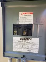
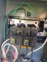
Electrical path: 2-pole 60A breaker in main panel; out to dedicated pool subpanel with 2 breakers - both 2-pole - 30A and 50A; 50A 2-pole out to the heater, 30A 2-pole out to pictured automation subpanel with a 2 pole 20A and a single-pole 20A; single-pole loads out to lighting junction box (and jumped in to automation board), 2-pole out to pump/blower


Can you show the whole system? What heater do you have? Where is the heater power coming from?
The system looks like it is about 16 years old (Maybe from about 2006). How old is everything? Can you show the door label?

See Ajw22's labeling job above. Heat pump is a Heatwave Superquiet. I''ve been here only a year, but it looks like the equipment varies in age. 12-16 years is probably accurate. Will add pics. Heat pump may be closer to 8 years.


Filter pump and Blower AUX2 is fed by 240V CB. Light1, Light2, and panel is fed by 120V CB. There is a neutral from the lights and from the panel.

It is not clear to me where the heater is powered from. Current NEC requires GFCI CB for pumps, gas heaters, and 120V lights. Assumption is you don;t have 12V LED lights.

All neutrals from the devices powered from a GFCI CB must connect back to the neutral connection on the CB and not the neutral bus. So the neutral from the light and from the panel should be wire nutted together with a white pigtail that connects to the 120V GFCI CB neutral screw.

240V equipment have two hot lines black/red and no white neutral line.

Is all the wire in the Load Center 12 gauge? There is no reason to replace stranded wire with solid wire if it is the proper gauge.

Your labeling is accurate. Thought the pump might only have one connection because it is not variable speed though. Wire is 12 gauge, I'll just clean it up at the connections. Thanks for confirming the neutral path. I was hoping to just separate the controller, as in B2 above, but looks like pigtail is the way to go. Looking at it in light of everyone's responses, I'm realizing there is only 60A coming into the sub-panel (pic attached), so I can't add any breakers without removing one. Pigtail is the only option, right?

There's just one neutral between the two lights in the subpanel, which may be taken care of at the junction box as you described in a separate post. I have to trim the hedges back quite a bit to get clear access to the junction box, so I have not opened it up yet. Definitely 120v, not 12v LED lights. I have to replace a 10" 120v Colorlogic 4.0 that got fried in the surge (lightning). Maybe I should just do a transformer and switch to a 12v light, but the 120v spa light is fine and I replaced the spa bulb recently. Will probably get a Hayward Astrolite for the 10" so I can change the bulb.


What breaker do you have feeding this sub panel?

Do you have a GFCI outlet at the light junction box?

It's fed by a subpanel with 2 breakers - both 2-pole - 30A and 50A. This subpanel was replaced last year. I believe the junction box is direct wired, no outlet nearby.


20221021_114733.jpg20221026_134514.jpg

Replace it with a single pole GFIC breaker. The neutral for the lights and the controller (top wire on the neutral buss bar) will have to be wired nutted together with a pig tail and the pigtail connected to the new breaker. You can not place more than one wire on the terminal of a breaker. Personally I like the WACO wiring blocks better than wire nuts.
Thanks! I've never trusted the blocks. They just seem too easy, but I should give them a try.
 

Attachments

  • 20221021_114741.jpg
    20221021_114741.jpg
    344.9 KB · Views: 19
  • equip w panel.jpg
    equip w panel.jpg
    336.9 KB · Views: 17
  • heat pump.jpg
    heat pump.jpg
    250.9 KB · Views: 16
  • main box and subpanel1.jpg
    main box and subpanel1.jpg
    194.4 KB · Views: 16
Replace the light breaker with a 15 amp GFCI breaker and then power the lights from that.

Change the pump breaker to GFCI

You can add more breakers to the AquaLogic panel.


There's a lot going on, so I would still recommend that you have an electrician verify everything is safe and up to code.
 
After a power surge did a lot of damage, I discovered I don't have a GFCI breaker for my pool lights. I've got to replace the regular QP type breaker with a GFCI breaker, but I'm a little confused by the wiring here (see pic).

Questions:

A) What's up with the neutral wiring? Does this look normal? Can I just
(1) pop in the appropriate new GFCI breaker,​
(2) attach the connected GFCI neutral-out to the neutral bus,​
(3) attach the black wire from the old breaker that leads to the Lights Relay to the new GFCI breaker, and​
Most importantly: I assume I should also (4) move the load's neutral wire (from Aux 1/Spa Light wire bundle) from the neutral bus to the GFCI neutral-in? Is that right? (I don't see a neutral wire for the main pool light, just the load out wire to the junction box.)​


B) Doing all that may leave two neutrals in that path, one from the automation board to the neutral bus and one connected in to the GFCI from the load on Aux 1 (Spa Light) and then out of the GFCI to the neutral bus. It's probably not ok to leave it like that, right? There's a jump wire from the Lights relay to Aux 1, then automation.
Should I change the wiring to
(1) two separate lines in from a 2-pole GFCI for each of the two lights (with no jump wire from Lights to Aux 1) and a third line directly from a separate regular breaker to the automation, or​
(2) just keep the two lights on a one-pole GFCI using the current wiring as is with the existing jump wire from the Lights relay to the Aux 1 relay, but move the automation board line-in wire directly to a regular breaker (not connected to Aux 1)?​


C) Anything else jump out at you that needs attention - aside from cleaning up the sloppy/exposed contacts on the relays? Maybe I should swap out the stranded wire for solid copper wherever possible. Probably should change the pump/heater/blower breaker to GFCI too, but no idea what to make of no neutrals at all on the load there.


View attachment 460699
Where is your GFCI? There does not appear to be one in the picture. It looks like the light is wired directly to the relay, not good.
 
I'm realizing there is only 60A coming into the sub-panel (pic attached), so I can't add any breakers without removing one. Pigtail is the only option, right?

You use actual loads and don't add up the CBs to determine actual capacity on a subpanel.

Your actual loads is around 18 amps between your pump, blower, lights and controller.

Adding another breaker and separating the lights and controller to separate breakers adds no additional loads to the panel.

Leave the controller on the existing 120V breaker and add a 120V GFCI CB for the lights.
 
Let's see what's in the junction box so we know what's what.

That's a few weeks away. Need to buy a pool light to install before I clear that out. I expect to find exactly what ajw22 described above in the junction box. That theory is supported by the 4 wires we see in the lighting conduit.
junction box.jpg


Replace the light breaker with a 15 amp GFCI breaker and then power the lights from that.

Change the pump breaker to GFCI

You can add more breakers to the AquaLogic panel.


There's a lot going on, so I would still recommend that you have an electrician verify everything is safe and up to code.
Probably will not change the pump breaker until the pump dies, if it's not required until then. No idea what to do with no neutrals there, and that is covered by home warranty. I feel like lights are a much bigger safety issue, pump not so much.

I'll have an electrician take a look eventually, but what fun would that be? Next you are going to tell me to stop cutting my own hair!

Box Cover.jpg
 
Probably will not change the pump breaker until the pump dies, if it's not required until then.

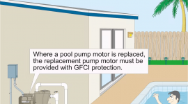
Changing the pump CB to a GFCI is easy. I don't understand your reluctance to increase the safety.

No idea what to do with no neutrals there, and that is covered by home warranty.

I don't understand what neutrals you are musing about.

A 240V pump does not have any neutrals.

I feel like lights are a much bigger safety issue, pump not so much.

Your pump is on and electrified much more then your lights are.
 
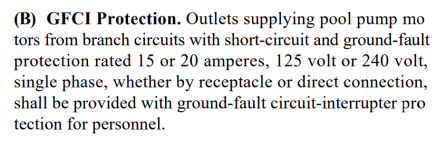
(B) GFCI Protection.

Outlets supplying pool pump motors from branch circuits with short-circuit and ground-fault protection rated 15 or 20 amperes, 125 volt or 240 volt, single phase, whether by receptacle or direct connection, shall be provided with ground-fault circuit-interrupter protection for personnel.


1667425913678.png
 

Enjoying this content?

Support TFP with a donation.

Give Support
Thread Status
Hello , This thread has been inactive for over 60 days. New postings here are unlikely to be seen or responded to by other members. For better visibility, consider Starting A New Thread.