Repairing VS Pump Drive PCB

Status
Not open for further replies.

OntarioCanada

Bronze Supporter
May 30, 2022
48
Ontario, Canada
Pool Size
50000
Surface
Vinyl
Chlorine
Salt Water Generator
SWG Type
Hayward Aqua Rite Pro (T-15)
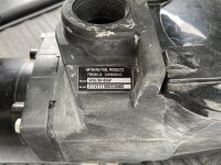
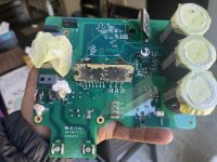
My drive died and now showing Drive Rev version as 0.00 on display and saying there is communication error between drive and display. Has anyone tried to repair this type of defect? Looks like a component on the drive PCB has failed and I don’t know which one.

If it is the IC that may have been fried due to voltage surge etc then can I get new IC and flash the firmware on it through JTAG?
 

Attachments

  • IMG_3581.jpeg
    IMG_3581.jpeg
    656.1 KB · Views: 25
  • IMG_3578.jpeg
    IMG_3578.jpeg
    626.4 KB · Views: 23
can you read the number off of chip U8? looks like that could be an rs485 transceiver chip, but I'm not familiar with the setup. what controller did the pcb come out of? [Edit] - looks like an Ecostar
 
It’s from Hayward Super Pump VS

I just took the PCB out to take pics, no water went in so everything visually looks fine. No swollen capacitors so I thinking the IC fried from surge or something similar and wondering I can read the flash, save and if I can find the IC then flash the code on there. I can solder and have multimeter and pickit 3 peogram and trying to see someone can point me in the right direction in identifying and replacing the broken components on this PCB.
 

Attachments

  • IMG_3659.jpeg
    IMG_3659.jpeg
    422.7 KB · Views: 15
  • IMG_3667.jpeg
    IMG_3667.jpeg
    487.6 KB · Views: 15
  • IMG_3668.jpeg
    IMG_3668.jpeg
    407.5 KB · Views: 16
  • IMG_3666.jpeg
    IMG_3666.jpeg
    322.2 KB · Views: 14
  • IMG_3660.jpeg
    IMG_3660.jpeg
    399.9 KB · Views: 15
  • IMG_3664.jpeg
    IMG_3664.jpeg
    358.9 KB · Views: 13
  • IMG_3662.jpeg
    IMG_3662.jpeg
    360.6 KB · Views: 14
  • IMG_3663.jpeg
    IMG_3663.jpeg
    421.5 KB · Views: 13
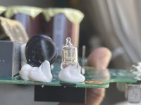
this a bulb or fuse? There seems to be no filament in there.

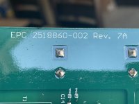
See numbers from U8
 

Attachments

  • IMG_3671.jpeg
    IMG_3671.jpeg
    295.6 KB · Views: 8
  • IMG_3670.jpeg
    IMG_3670.jpeg
    242.8 KB · Views: 6
  • IMG_3669.jpeg
    IMG_3669.jpeg
    269.7 KB · Views: 7
  • IMG_3675.jpeg
    IMG_3675.jpeg
    418.4 KB · Views: 8
There are three boards:

1) Display board there the keys are attached to
2) there is a board under the display then
3) the third that connects to the motor.

Pics are shared above are of the board where the motor plugs into (3) and that’s where 110v goes into.

Attached is the middle board (2) that has a connector for wire to display board (1) and it says RS485 next to that connector

2 and 3 are connected using 4 wire connector coming from board 2 (white) going on to JP1 connector in my original pics.

Are you thinking it’s board 3 or board 2 that may be the culprit?
 

Attachments

  • IMG_3679.jpeg
    IMG_3679.jpeg
    488.1 KB · Views: 9
  • IMG_3680.jpeg
    IMG_3680.jpeg
    465.5 KB · Views: 11
Last edited:
I misunderstood, I didn't realize all of these boards were in the pump itself... I thought your display board was similar to a wall-mounted Pentair indoor controller that talked to some other outdoor controller - or the pump itself - over rs485. The U8 chip that I was asking about is from the blue board in your first pic... the U8 chip picture you attached looks like it's from the drive board itself - and the chip is just a comparator.

I don't have any experience with these pumps, but I wonder if the top 2 boards might each have an rs485 chip (the middle board has a rs485 connector, but the actual chip might be U8 up on the top blue board, I can't tell)? So I'm thinking the communication error you're seeing could be that the top 2 boards can't talk to each other, OR it may be that the top/middle board can't talk to the bottom pump driver board - I don't really know.

You also asked about DS1, which looks like a neon bulb to me... but I wasn't able to determine the part number or manufacturer. It's the first component the line level voltage goes through, so it appears to be part of the input protection for the motor board (along with DS1 there are also appear to be two MOVs and a PTC, which also used for input protection). Finally, there's a high voltage slot cut in the board, between DS1's legs, which tells me it's trying to protect against a high voltage (neon bulbs can be used for input protection because they have a high breakdown voltage). It's also possible that it's just as just an indicator (but I don't know where you'd see it lit up), or that it's not a neon bulb at all.

You were talking about reading/re-flashing chips but 1. I don't think you're at a point where you know that's your problem, 2. I'd bet the microcontroller flash is protected, so you could re-flash it but you can't read it, and 3. I doubt the firmware is available.

If it were my pump I'd try to figure out if the top 2 boards each have a comm chip (look up the part number for U8 on the blue board, and search for a similar chip on the middle board). And then I'd use a multimeter to make sure the bottom board is getting power after DS1. It sounds like you know your way around electronics but be careful... these things generate high voltages and although I can't see what the voltage ratings are, there are 3 large dangerous capacitors in there
 
Thanks for the tips!

I will try to spend some time and see if I can find what may have gotten fried due to surge.

The three large caps are 420v and yes I wait for them to discharge, confirm with multimeter then only I touch the board :)
 
  • Like
Reactions: ogdento
Status
Not open for further replies.
Thread Status
Hello , This thread has been inactive for over 60 days. New postings here are unlikely to be seen or responded to by other members. For better visibility, consider Starting A New Thread.