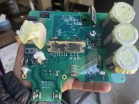
I misunderstood, I didn't realize all of these boards were in the pump itself... I thought your display board was similar to a wall-mounted Pentair indoor controller that talked to some other outdoor controller - or the pump itself - over rs485. The U8 chip that I was asking about is from the blue board in your first pic... the U8 chip picture you attached looks like it's from the drive board itself - and the chip is just a comparator.
I don't have any experience with these pumps, but I wonder if the top 2 boards might each have an rs485 chip (the middle board has a rs485 connector, but the actual chip might be U8 up on the top blue board, I can't tell)? So I'm thinking the communication error you're seeing could be that the top 2 boards can't talk to each other, OR it may be that the top/middle board can't talk to the bottom pump driver board - I don't really know.
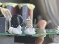
You also asked about DS1, which looks like a neon bulb to me... but I wasn't able to determine the part number or manufacturer. It's the first component the line level voltage goes through, so it appears to be part of the input protection for the motor board (along with DS1 there are also appear to be two MOVs and a PTC, which also used for input protection). Finally, there's a high voltage slot cut in the board, between DS1's legs, which tells me it's trying to protect against a high voltage (neon bulbs can be used for input protection because they have a high breakdown voltage). It's also possible that it's just as just an indicator (but I don't know where you'd see it lit up), or that it's not a neon bulb at all.
You were talking about reading/re-flashing chips but 1. I don't think you're at a point where you know that's your problem, 2. I'd bet the microcontroller flash is protected, so you could re-flash it but you can't read it, and 3. I doubt the firmware is available.
If it were my pump I'd try to figure out if the top 2 boards each have a comm chip (look up the part number for U8 on the blue board, and search for a similar chip on the middle board). And then I'd use a multimeter to make sure the bottom board is getting power after DS1. It sounds like you know your way around electronics but be careful... these things generate high voltages and although I can't see what the voltage ratings are, there are 3 large dangerous capacitors in there