Pump trips circuit breaker after hours of running

DingleFritzer

Member
Jan 19, 2025
6
Florida
Hey everyone, I’m running out of ideas here. I’ve had two electricians come out and verify everything is working fine on the electrical side. It pulls the correct amperage, it never trips the GFCI outlet, it trips after/while raining and if it’s dry.

I have a Doheny pump that’s maybe a month old that recently started tripping the circuit breaker after running 7-12 hours. I cleaned out the internal basket filter, I’ve run it through a plug with a timer, I’ve tried running it directly plugged into the outlet. I haven’t noticed any unusual noises, nor have I identified a specific external variable’s presence when it kicks off. I’m running out of ideas and I’d prefer not spending upwards of $200 on another electrician. Thanks for the help!
 
Welcome to TFP.

Show us pictures of the pump, motor data plate, plug and outlet connections, and circuit breaker and panel as a start.

Give us data - what is the measured voltage and amps?

Has the CB been replaced?

What amp is the CB and what size wire is the circuit?

You have a multimeter and a clamp on ammeter?
 
Last edited:
Welcome to TFP.

Show us pictures of the pump, motor data plate, plug and outlet connections, and circuit breaker and panel as a start.

Give us data - what is the measured amps?

Has the CB been replaced?

What amp is the CB and what size wire is the circuit?

You have a multimeter and a clamp on ammeter?

I can take pictures later today, but

10 amp pump pulling 10 amps measured via clamp.

Both electricians agreed that the CB is operating properly and recommended against changing saying, “I’ll happily take your money, but the breaker is working properly and changing it won’t do anything.”

15 amp breaker. Neither electrician said anything about the wire after looking at everything so I’m assuming the proper gauge is being used.

Yes, multimeter used by both electricians and myself confirmed current flowing at correct level. Ammeter, used by all parties, confirmed amperage being pulled at 10.
When were your amp draw measurements taken? Clean pump basket, clean filter, on a cold start…..or with a dirty pump basket, dirty filter, after 5 hours of run time? Run time and loading issues will make a difference on how hard the system is needing to work thus effecting the amp draw.
 
When were your amp draw measurements taken? Clean pump basket, clean filter, on a cold start…..or with a dirty pump basket, dirty filter, after 5 hours of run time? Run time and loading issues will make a difference on how hard the system is needing to work thus effecting the amp draw.

Within 30 minutes of starting up the pump.
All baskets are cleaned of debris, filter is backwashed. I’m planning on starting it up today and taking an amperage read every hour to see when the load increase starts to happen, and if it consistently starts around the same timeframe.
 
It pulls the correct amperage, it never trips the GFCI outlet, it trips after/while raining and if it’s dry.
There are two types of trip mechanism.
1) Thermal.
2) Magnetic.

A thermal trip is caused by heat due to excessive amperage.

If you are not exceeding the breaker rating, it should not trip (assumes normal environmental temperature).

It might be a defective breaker or maybe a short to ground causing the magnetic trip.

1737301365731.png
1737301701834.png

myths dispelled
Having discussed basic breaker operation and having demonstrated the independence of the thermal and magnetic mechanisms it is now easy to step through the myths and the physical reason(s) that each one is fiction.
1. T-M breakers trip upon reaching the rated current.

T-M breakers trip according to a trip curve, which includes both 135 percent and 200 percent trip times.

At 135 percent of rated current, the breaker must trip in 1 hour or less.


The trip curve is non linear as loads approach the breaker ratings (FIGURE 1), therefore, at even 5 percent above trip rating, there is no guarantee that the breaker will ever trip.

2. T-M circuit breakers always trip immediately.

These breakers trip thermally in seconds to minutes (depending on current level), per the published trip curve, in overload situations.

In short circuit situations, trip times can be several cycles.
 

Attachments

  • CircuitBreakerMyths_web.pdf
    376.8 KB · Views: 1
A solenoid placed in series with a bimetal thermal actuator creates a "two-step" time/current protection characteristic, meaning it can react quickly to high, sudden overcurrents (triggered by the solenoid) while also responding to prolonged lower-level overloads through the slower thermal mechanism of the bimetal strip; essentially providing fast protection against short circuits and slower protection against prolonged overloads.

Solenoid Function:
When a large surge of current flows through the circuit, the solenoid rapidly activates due to the strong magnetic field generated, instantly triggering the release mechanism to cut off power.

Bimetal Thermal Actuator:

This component consists of a bimetal strip that bends when heated by excessive current over time.

When the strip bends enough, it activates a mechanism to interrupt the circuit, but this process takes longer compared to the solenoid's response.

Note that breakers and switches have to be derated in high temperature conditions.

According to the NEC, circuit breakers should be "temperature derated" when the ambient operating temperature exceeds 40°C (104°F), meaning you need to reduce the allowable current rating of the breaker based on the higher temperature environment; this is typically done by consulting manufacturer's data for the specific breaker model and applying the necessary derating factor.

Below is an example of conductor derating factors based on ambient temp.
1737302349173.png
1737302767187.png
1737303632997.png
 
Last edited:
Both electricians agreed that the CB is operating properly and recommended against changing saying, “I’ll happily take your money, but the breaker is working properly and changing it won’t do anything.”

Ammeter, used by all parties, confirmed amperage being pulled at 10.
They can't really tell if it is working properly.

They would have to load it at full capacity (15 amps) and watch it operate for at least an hour to tell if it is functioning correctly.

They would have to test it like they do at a factory that verifies the trip curves by increasing the current and watching for the trip time.

At 15 amps, the breaker should not trip (ambient temperature less than 40°C (104°F)).

If the amps are more than 15 but less than 20.25, then the breaker can trip, but it does not have to.

at 135%, the breaker must trip within 1 hour. (15 x 1.35 = 20.25 amps).

At 30 amps (200%), the breaker must trip within 2 minutes.

The magnetic trip will take about 140 to 250 amps to trigger the trip and this will happen in a fraction of a second (Maybe about 17 to 50 milliseconds).

1737329704219.png

If the amps are really at 10 amps, the breaker is likely to be defective or there is some sort of intermittent short circuit causing the magnetic trip part of the breaker.

A 15 amp breaker should be able to operate continuously at 15 amps at less than 104 degrees F.

I would replace the breaker.

You can set up a monitor on the line to look for high current spikes caused by an intermittent short to ground, but that is difficult to do.
 
Last edited:
What is the voltage at the pump terminals during operation?

Do you have a non-contact temperature sensor or thermal camera that you can use to check the temperature of the circuit breaker when it trips?
 
Last edited:
Note that a dirty filter or clogged baskets do not increase amperage.

In fact, amperage is highest at the lowest system resistance because the flow is highest.

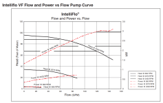
Below is an example of an Intelliflo at 3,450 RPM (Full Speed).

At about 88 feet of head, the flow is about 60 GPM and the power is about 2,250 watts.

If the "Wire to Water" Efficiency is 51%, then the useful power is 1,148 watts.

At about 67 feet of head, the flow is about 120 GPM and the power is about 3,000 watts.

If the "Wire to Water" Efficiency is 58%, then the useful power is 1,740 watts.

So, less head (restriction) creates more flow and uses more power due to more flow.

Power used is a combination of flow and head loss.

You are changing two variables at once.

You are increasing the flow at a higher ratio than you are reducing head loss.

If you increased head loss and kept the same flow, then power usage would increase.

You also have to account for the "Wire to Water" Efficiency, which affects how much power is used at each operating point.

For the Intelliflo3, the "Wire to Water" Efficiency is about 51% at 60 GPM, about 56% at 120 GPM and about 58% at 100 GPM.

You can get a rough idea about the useful power change using the ratio of head loss x the ratio of flow.

(67/88) X (120/60) X 1,148 watts = 1,748 watts useful power delivered to the water.

1,748/0.58 = 3,014 watts used total.
1737318866604.png

1737319138248.png


IntelliFlo® VF Variable Flow Pump.

1737320797954.png


Note that the graph says "Intersection point represents the most efficient operating point at maximum speed".

However, I think that this is incorrect.

The most efficient operating point is the highest point on the green curve.

The graphs are using different Y-axes, so the intersection is irrelevant.
 

Attachments

  • pentair-if3-sell-sheet-022023.pdf
    4.1 MB · Views: 0
Last edited:

Enjoying this content?

Support TFP with a donation.

Give Support
Notes from pump start to discovered CB trip
“Others” being the other circuit breakers on the panel. OAT dropped significantly throughout the day which reflects on temp readings. Dry day, no rain.
Amperage measured with Klein CL220
Temps measured with Klein Infrared Thermometer.
All measurements taken at same point.

Pump first on 1150

1155 @9.7

1255 @9.8

1345 @9.8

1550 @9.8 and 65F others around 60

1700 @9.8 and 61F others around 57

1800 @9.8 and 55F others around 48-50

1905 @9.8 and 54F others 45-48

2000 @9.8 and 50F others 43-48

2055 @9.8 and 48F other 38-44

2150 @9.8 and 43f others 36-41

2226 checked to see if pump was still running and it was off

2228 38F others 33-36
 
Probably a bad breaker or an intermittent short to ground.

Try a new breaker and if it trips, then you need to dig into the wiring to look for short to ground.

Maybe a defective pump that has a short to ground.
 
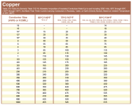
The wire size can be 14 AWG up to 67 feet. 15 amps ampacity plus a 3% voltage drop limit.

The wire size can be 12 AWG up to 103 feet. 20 amps ampacity plus a 3% voltage drop limit.

What is the wire size and length from the breaker to the pump?

If we assume 100 feet of #12 AWG wire, the short circuit maximum amperage is estimated at;

V = IR

120 = (200 feet x 0.0019) x (Amps)

120/0.38 = 315A.

So, a solid short to ground can generate about 315 amps of current.

A partial or weak short to ground will produce lower amps depending on how much contact the hot line has with the ground.

It takes about 140 amps to trip the magnetic part of the trip mechanism.

So, a short to ground that creates a brief short to ground at less than 140 amps might not trip the magnetic trip mechanism.


1737386193379.png
* Small Conductors.
Unless specifically permitted in 240.4(E) through (G), the overcurrent protection shall not exceed 15 amperes for 14 AWG, 20 amperes for 12 AWG, and 30 amperes for 10 AWG copper; or 15 amperes for 12 AWG and 25 amperes for 10 AWG aluminum and copper-clad aluminum after any correction factors for ambient temperature and number of conductors have been applied.

1737386290877.png
1737386334738.png
 
Last edited:
I’ll have to swap the breaker in a few days after this cold snap. I think my wife would kill me if I turned off power to the house right now lol. I’ll make sure to come back with the results though.

How would I determine a short to ground between the breaker and pump vs a short to ground issue via a defective pump?
 
How would I determine a short to ground between the breaker and pump vs a short to ground issue via a defective pump?
An intermittent short is difficult to track down.

Basically, separate and isolate all hot wires and check for continuity to ground.

This is involved and requires some knowledge of working with electrical wiring because you have to take everything apart and look for damage and check for continuity to ground and then put everything back together.
 
Check to see if the breaker is an "Arc-Fault" Type of Breaker.

Some Breakers are just thermal-magnetic and you can add on ground fault and/or arc fault.

An Arc-Fault Breaker trips based on certain characteristics in the power profile that would be consistent with an arcing wire.

Arc Fault breakers are not required outdoors and they can be associated with nuisance trips, so if the breaker is Arc-Fault, you might want to replace it with a Non-Arc-Fault Breaker.

 
Last edited:
With intermittent problems it is often more economical to just replace the wiring and CB.
 

Enjoying this content?

Support TFP with a donation.

Give Support