Pool Light Tripping GFCI Breaker

Kritheo

New member
Dec 14, 2022
2
Oklahoma
Pool Size
26000
Surface
Plaster
Chlorine
Liquid Chlorine
Hello,

We have a remodeled pool with fresh electrical which was all installed by a professional licensed electrician. I will spare you the details on having to hire a 2nd electrician and move to the issue. We tried to get the electricians to install GFCI breakers to both the pump and the pool light. The pump is a Jandy VS 165 and we have a Cutler Hammer breaker Box. This can not utilize the recommended Siemens GFCI BR breaker. The first breaker our electrician used kept tripping after some time however, it has stabilized with an Eaton CH breaker. That leads to the light which was also completely rewired. The light is on a Eaton CH GFCI breaker that connects to a couple of j-boxes then to an Intermatic PX300 12v transformer. The transformer is brand new and the breakers are brand new. The transformer then goes to another jbox on the pool deck and then down to the light itself. We have swapped to a 12v blub. Every time we try to use the light it trips. I started isolating the issue and opened the deck box and removed the pool light from the equation leaving the 12v wires open and it still tripped. I then removed the leads from the deck j-box at the transformer from the black and white (for 12 v) and it still trips. This means the transformer is somehow where the fault is located. I removed my 120v wires from the transformer and they do not trip. It is also worth noting that along the way back I used a multimeter to test continuity for any shorts and none were found in the wiring and nothing alarmed until connected to the transformer. I suspect my breaker box is the actual issue. After watching several guide videos and reading up on the documentation for the pool pump, the transformer and some general wiring I noticed that my breaker box does not have a separate common and ground bus bar. This means all of my grounds and commons are connected at the breaker box. I am pretty sure this is what is tripping my pool light GFCI however, that would lead me to question why it is not tripping my pump GFCI as well. I have some photos attached. This was the result of 2 separate electricians after asking them to make sure that it is up to code and done correctly. I am not saying it is not however, there appears to be a few glaring issues. We want it to be safe and would like to be able to use the light while we swim. I am sure I left some stuff out but would appreciate any information as to why the light GFCI is tripping but not the pump.

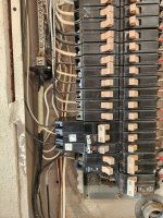
Main Breaker Panel
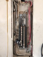
20230724_082113.jpg
Close of GFCI Breakers
20230724_082125.jpg
J-box exiting garage
20230724_095655.jpg
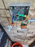
j-box at pool equipment.
20230724_082322.jpg
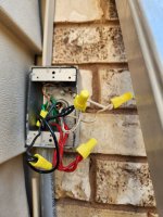
Switches for pump and light
20230724_082443.jpg
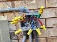
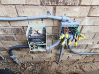
Transformer and J-box at equipment
20230724_082302.jpg
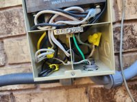
Close up of Transformer
20230724_082328.jpg
 
In one photo it shows a light swtch and a receptacle but unable to see what type of receptacle. If that is a GFCI receptacle and connected to your light circuit, then you should not have 2 GFCI devices on the same circuit.
 
  • Like
Reactions: Kritheo
Welcome to TFP.

.The light is on a Eaton CH GFCI breaker that connects to a couple of j-boxes then to an Intermatic PX300 12v transformer. The transformer is brand new and the breakers are brand new. The transformer then goes to another jbox on the pool deck and then down to the light itself. We have swapped to a 12v blub. Every time we try to use the light it trips. I started isolating the issue and opened the deck box and removed the pool light from the equation leaving the 12v wires open and it still tripped. I then removed the leads from the deck j-box at the transformer from the black and white (for 12 v) and it still trips. This means the transformer is somehow where the fault is located. I removed my 120v wires from the transformer and they do not trip. It is also worth noting that along the way back I used a multimeter to test continuity for any shorts and none were found in the wiring and nothing alarmed until connected to the transformer.

The transformer neutral is misplaced and connected to the neutral bar when it should be connected to the neutral screw on it's GFCI CB.

I cannot follow how the transformer neutral gets from the transformer box to the panel to the GFCI through the various connections and wire nuts. But this is a common mistake. The electrician forgets that he is wiring a GFCI circuit and connects the neutral to other neutrals at a convenient point instead of wiring it to the CB.

I was reviewing a subpanel wiring the other day done by a very good electrician and pointed out he had a GFCI light neutral connected to the neutral bar instead of the GFCI CB.

Carefully trace the transformer neutral connection and you will find your problem.

I suspect my breaker box is the actual issue.

No, it is not your issue.

After watching several guide videos and reading up on the documentation for the pool pump, the transformer and some general wiring I noticed that my breaker box does not have a separate common and ground bus bar. This means all of my grounds and commons are connected at the breaker box.

You have to be careful trying to learn from Youtube.

In the main electrical service panel, which is what you showed, you can connect ground and neutral wires to the same bar. All subsequent sub panels in the house must have separate ground and neutral bars. Many panels come with a single bar and the electrician installs another bar in the panel if separate ground and neutrals are to be used.

So there is nothing wrong with your main panel and that is not the cause of your GFCI trip.
I am pretty sure this is what is tripping my pool light GFCI however, that would lead me to question why it is not tripping my pump GFCI as well.

Your pump is a 240V circuit that does not use a neutral wire.

With GFCI CBs both wires that carry power must run through the CB.

On a 240V circuit that is easy to see with two hot wires.

On a 120V circuit a non-GFCI CB only connects to the hot wire and the neutral is run to the neutral bar. However when it is a GFCI CB the hot and the neutral wire must both be connected to the GFCI CB.

This was the result of 2 separate electricians after asking them to make sure that it is up to code and done correctly.

Two people wiring a panel leads to this type of mistake.

Go trace the transformer neutral and you will find your problem.
 
Last edited:
Let's begin at the transformer.

You have two conduits coming into the bottom right side.

Looks like the front one is to the 12V lights and the rear one is to the CB power.

A pool rated transformer is required to keep the high voltage separate from the low voltage for safety. You can see the separation with the divider between the left and right side lower wiring compartment. However your electrician did not understand the requirements of a pool rated transformer and ran both high voltage and low voltage to the same side.

The 12V conduit to the pool lights should be wired through a knockout on the left side.

Instead he ran wire through the metal divider from the high voltage side to connect to the 12V transformer output.

That white neutral line on the lower right with a yellow wire nut tied to the black wire must lead directly to the GFCI CB feeding the black hot wire. Trace it and I think you will find it does not.

20230724_082328-jpg.519607
 
Last edited:
  • Like
Reactions: Kritheo
Where does this switch box connect to? The conduit runs out to the right of the pic.

How did the electrician get the pump circuit and the light circuit into the same box and conduit?

Is the light switch switching the 120V into the transformer or the 12V out from the transformer?

From looking at the J-Box wiring next to the transformer it looks like the light switch is wired into the J-Box at the 12V side. If so this is a BIG NO NO to mix high voltage and low voltage in the same switch box.

High voltage and low voltage wires should never be mixed in any electrical boxes or conduit lines.


20230724_082443-jpg.519608
 
  • Like
Reactions: Kritheo
I see orange wires coming into the J-Box which is the color wires used in the switch box. This is what leads me to believe that the light power is being switched on the 12V side.

The light J-Box should only have low voltage wires.

20230724_082322-jpg.519606
 
  • Like
Reactions: Kritheo
The light neutral is misplaced and connected to the neutral bar when it should be connected to the neutral screw on it's GFCI CB.
+1, it definitely is. Red markup is current neutral, white is what you'll need to do. It will be too short so you will need to add a length of white with wire nut in the main panel (allowed with your current box fill) and land the neutral on the gfci breaker.
1691159729537~2.jpg
which was all installed by a professional licensed electrician.
Highly questionable 🤔, in addition to what Allen noted, they used Romex in conduit(a "wet" area per nec) which is not allowed
Close up of Transformer
+1 for Allen's comment. This needs to be redone which will unfortunately require new wire and conduit so that the line voltage goes into a knocker on the left side of the transformer. If for no other reason, the transformer will "buzz" enough that it could wear through the sheathing of the wires passing thru the protective barrier
 
  • Like
Reactions: Kritheo
That white neutral line on the lower right with a yellow wire nut tied to the black wire must lead directly to the GFCI CB feeding the black hot wire.
The wire nuts in the lower right of the transformer look to go to the light
From looking at the J-Box wiring next to the transformer it looks like the light switch is wired into the J-Box at the 12V side.
I think the switch is correct, those wires enter the low voltage side of the transformer then slip thru the divider plate to the line voltage side
 
  • Like
Reactions: Kritheo
The wire nuts in the lower right of the transformer look to go to the light

I think the switch is correct, those wires enter the low voltage side of the transformer then slip thru the divider plate to the line voltage side

I think I got the transformer high voltage and low voltage compartments reversed. Left should be high voltage and right should be low voltage. Electrician brought both up through the right low voltage side.

I can't follow all the wiring but still am suspicious of the light switch. Where did the electrician get the pump wires and light wires into one conduit to the light switch box? I would have expected a conduit for each switch.
 
  • Like
Reactions: Kritheo
Where did the electrician get the pump wires and light wires into one conduit to the light switch box?
The two romex cables (which should also be checked as they are white which is typically #14 and they should be yellow #12 , unless they are just real old) come out of the main and both exit into the back of the single gang outlet box
20230724_095655.jpg
From there it appears there are 2 black, a red a green a white and a white taped red that drop into conduit and come back up to the center bottom of the 2 gang junction box.
20230724_082322.jpg
 
  • Like
Reactions: Kritheo

Enjoying this content?

Support TFP with a donation.

Give Support
The two romex cables (which should also be checked as they are white which is typically #14 and they should be yellow #12 , unless they are just real old) come out of the main and both exit into the back of the single gang outlet box

From there it appears there are 2 black, a red a green a white and a white taped red that drop into conduit and come back up to the center bottom of the 2 gang junction box.

I see now. I thought that 2 gang box had wires from the 12V pool lights.

I wish more electricians labeled the wires in these complex boxes. I have anyone who works on my stuff label every wire. And when I need to dive in and figure out wiring I label everything I figure out so a few years later when I need to look at it again I have some clues what is going on.

@Kritheo should look into the pump and light GFCI CB being 20A and that 12 gauge wire has been used, not 14 gauge. Or possibley downgrade the light GFCI CB to 15A to match the 14 gauge wire if used.
 
  • Like
Reactions: Kritheo
Thank you all for the responses, I am going to go through all of them and follow the wiring this weekend. I apologize for going silent as I had to go out of town for a few days and did not have time to go through everything posted. I will update with my findings as I go through the wiring and compare your notes.
 
Thread Status
Hello , This thread has been inactive for over 60 days. New postings here are unlikely to be seen or responded to by other members. For better visibility, consider Starting A New Thread.