Pentair Minimax 100 burner will not light

tjmlack

Member
Jun 13, 2024
14
Ohio
I have a Pentair Minimax 100, natural gas, pool heater. The pilot will light and stay lit but when the thermostat is turned to demand heat the burner doesn't ignite. I have 545 mv from the thermopile and have continuity through the circuit to the valve when heat is demanded. Is 545 mv enough to open the gas valve? Any suggestions on what to check next?
Thanks.
What is the voltage at the MV/PV to MV terminals when the thermostat is turned up enough to call for heat. It takes about 100mV to keep the pilot lit, another 400 or so to open the main valve and then another 100 in reserve. Usually it takes 600+ to operate a millivolt heater.
 
What is the voltage at the MV/PV to MV terminals when the thermostat is turned up enough to call for heat. It takes about 100mV to keep the pilot lit, another 400 or so to open the main valve and then another 100 in reserve. Usually it takes 600+ to operate a millivolt heater.
When measured at the connection of the thermopile leads to the gas valve it's 545 mv. If 600+ is needed could the thermopile be bad?
 

Attachments

  • IMG_2046.JPG
    IMG_2046.JPG
    423.7 KB · Views: 12
What is the mv reading from TP to TH?
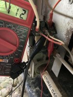
Here are the mv readings
Photo 1 mv from thermopile, pilot lit 527 mv
Photo 2 mv to TP-TH no heat demand 16 mv
Photo 3 mv to TP-TH when thermostat in heat demand mode 112 mv.

I hope I have the correct connections and units.
 

Attachments

  • Photo 2 mv across TP-TH No Demand.JPG
    Photo 2 mv across TP-TH No Demand.JPG
    170.5 KB · Views: 11
  • Photo 1 mv from Thermopile.JPG
    Photo 1 mv from Thermopile.JPG
    211 KB · Views: 12
  • Photo 3 mv across TP-TH Heat Demand.JPG
    Photo 3 mv across TP-TH Heat Demand.JPG
    200.9 KB · Views: 12
This should be the manual for your heater https://www.pentair.com/content/dam...als/training/MiniMax 75-100 Owners Manual.pdf Wiring diagram for millivolt is on page 20. It seems that you are dropping more than 400 mv across your operating/safety ciruit. Suggest that you measure from TP with one lead through all of the operating/safety circuit components that the white TP/TH wire goes through in order to see where the voltage drop is occuring. Pay attention to corroded component connection contacts but the problem may also be internal component contacts. They are all open/closed switches with the exception of the thermal cutoff.
 
Thanks for getting back. Here are my measurements:
TP to:

TP-TH 526 mv

Hi Limit 513 mv

Press Sw 515 mv

On/Off 515 mv

Temp Cont 515 mv

I cleaned all connections. When pilot was lit took about 20 minutes for thermopile to level out at 525 mv.
 
Sorry, have been out of town for a family reunion for the last 2 weeks. Your reported mv measurements do not seem to make any sense. Your previous 3 photos clearly show that you are dropping 415 mv from TP to TH. Are you now showing 515mv from TP to both sides of the Temp control and also from TP to TH at the gas valve?
 

Enjoying this content?

Support TFP with a donation.

Give Support
I can't explain the 415 mv reading in my previous post so I went back, installed the heater and measured again. Should I be getting the same mv reading of 526 mv across all the components in the safety circuit? What mv value is needed to open the gas valve?
 
Appreciate your patience.
With the heater installed and pressure switch closed I am getting 519 mv at the TP-TH to TP connection of the thermopile to the gas valve with no demand for heat. When the thermostat is rotated to demand heating the voltage drops to 479 mv. The TP to TH is 231 mv.
If I should get 300-400 mv from TP to TH could there be a problem with the gas valve? I bring the heater in the garage during the winter. Could there be something in the valve, ie. dirt, preventing the valve from opening? Is the valve something that can be repaired? Thanks.
 
Gas valves are not serviceable. If a gas valve is opened it must be replaced.
 
  • Like
Reactions: 1poolman1
You are dropping too much voltage in the operating/safety circuit! You powerpile is generating 519 mv (could be better... Do you have a good strong pilot flame that is 2 shades of blue with no yellow in it and is the powerpile fairly new? Put one meter lead on TP and check voltages on the downstream side of temp control, on-off switch, thermal cut-off, pressure switch, safety shut-off and high limit to see where you are dropping the voltage. You could also check the voltage drop across each component individually to see which component(s) are losing the most voltage. Please report voltages and voltage drops.
 
I did replace the thermopile several weeks ago and it's putting out 632 mv. The pilot flame is a steady, solid blue (photo below). A diagram of the operating/safety circuit with mv measurements from TP to all components is also below. The differences in voltages maybe from my VOM meter bouncing around but don't seem to be to out of line. If there was a problem what king of voltage drop would you expect? If too much I'd expect a component problem. Also, when I go back to the heater the pilot flame after a couple of days is out and I have to relight to take more measurements.
 

Attachments

  • Minimax 100 millivolt measurements.pdf
    459.3 KB · Views: 4
  • Heater Pilot Flame.JPG
    Heater Pilot Flame.JPG
    500.6 KB · Views: 1
I have the red wire from the thermopile connected at TP and the white wire to the TP/TH. I removed the red wire at TP and the wire from TH. The resistance between TP and TH is 2.3 ohms. What should it be?
 
Sorry, your original photos show the white thermopile wire connected at TP. 2.3 ohms between TP and TH with no wires connected is within normal range for a millivolt gas valve. Reattach thermopile wire to TP. Measure millivolts from TP to the unattached red/orange? wire at TH. If you are still showing 500+ millivolts, attach red/orange wire to TH and measure millivolts from TP to TH with the red/orange wire attached. What millivolt reading does it show with all wires attached?
 
I am at a loss to explain why my readings are so inconsistent each time I go out to take measurements. It doesn't help in trying to figure out what's going on.
Here are the measurements from today.
Voltage from thermopile disconnected from valve - 630 mv
Voltage at valve TP/TH and TP - 476 mv
Voltage from TP to unattached Orange wire from TH - 475 mv
Voltage from TP to TH with Orange wire connected - 62 mv

Is there any way to check the gas valve? Maybe remove the operating/safety circuit and put a jumper wire across TP/TH to TH?
 

Enjoying this content?

Support TFP with a donation.

Give Support
Thread Status
Hello , This thread has been inactive for over 60 days. New postings here are unlikely to be seen or responded to by other members. For better visibility, consider Starting A New Thread.