Just installed a Pentair Easytouch to control my pool. Love it already but the installer didn’t have a GFCI for the side so we used a regular outlet until I could get one the next day. Regular out works fine and had power…two white wires, two black wires and a ground. Today I tried installing the GFCI outlet and it won’t let me reset or test it.
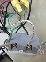
Line Black going to dedicated breaker
Load Black going to something up top on the panel
White neutral to panel neutrals
White neutral coming into panel
Green ground going from outlet to panel ground bar
This setup works for the non GFCI. Why wouldn’t it for a GFCI?
Line Black going to dedicated breaker
Load Black going to something up top on the panel
White neutral to panel neutrals
White neutral coming into panel
Green ground going from outlet to panel ground bar
This setup works for the non GFCI. Why wouldn’t it for a GFCI?