0 V across there
Failed timer, should manual switch still work?
- Thread starter brew4eagle
- Start date
You are using an out of date browser. It may not display this or other websites correctly.
You should upgrade or use an alternative browser.
You should upgrade or use an alternative browser.
- Jul 21, 2013
- 54,775
- Pool Size
- 35000
- Surface
- Plaster
- Chlorine
- Salt Water Generator
- SWG Type
- Pentair Intellichlor IC-60
And current NEC requires a GFCI CB for pump for safety.
 www.troublefreepool.com
Electrical GFCI - Further Reading
- Jul 21, 2013
- 54,775
- Pool Size
- 35000
- Surface
- Plaster
- Chlorine
- Salt Water Generator
- SWG Type
- Pentair Intellichlor IC-60
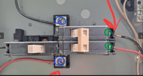
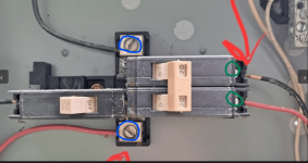
If the CB is in the position in the picture it is OFF.0 V across there
The lever has to be to the left for the CB power to be ON.
Yes, I had checked it with switch ON, just took pics while OFFIf the CB is in the position in the picture it is OFF.
The lever has to be to the left for the CB power to be ON.
- Jul 21, 2013
- 54,775
- Pool Size
- 35000
- Surface
- Plaster
- Chlorine
- Salt Water Generator
- SWG Type
- Pentair Intellichlor IC-60
Yes, I had checked it with switch ON, just took pics while OFF
Then your CB failed.
Replace it with a 20A GFCI CB.
- Jul 21, 2013
- 54,775
- Pool Size
- 35000
- Surface
- Plaster
- Chlorine
- Salt Water Generator
- SWG Type
- Pentair Intellichlor IC-60
Also to confirm, with the CB switched on I have no continuity across the green circles you drew. Also indicates it's bad?Then your CB failed.
Replace it with a 20A GFCI CB.
Yes, 240V at blue circles
- Jul 21, 2013
- 54,775
- Pool Size
- 35000
- Surface
- Plaster
- Chlorine
- Salt Water Generator
- SWG Type
- Pentair Intellichlor IC-60
Also to confirm, with the CB switched on I have no continuity across the green circles you drew. Also indicates it's bad?
BE CAREFUL. YOU ARE POKING AROUND LIVE 240 VOLTS!
The CB connects continuity from the bus bar contacts at A or B to the CB outputs at C and D.
Do not try and test continuity with A and B having 240V live.

- Jul 21, 2013
- 54,775
- Pool Size
- 35000
- Surface
- Plaster
- Chlorine
- Salt Water Generator
- SWG Type
- Pentair Intellichlor IC-60
Yes, 240V at blue circles
You have power into the CB panel.
That CB is old and not to current code and needs to be replaced.
- Jul 21, 2013
- 54,775
- Pool Size
- 35000
- Surface
- Plaster
- Chlorine
- Salt Water Generator
- SWG Type
- Pentair Intellichlor IC-60
Thanks so much for the assistance! I have the CB removed and headed to THD. Will bring up to code and will report back with results. Just started raining so will wait for the install of new CB.You have power into the CB panel.
That CB is old and not to current code and needs to be replaced.
NoI have power getting to the pool timer, however the motor gears are not turning. Tried to help them move via the gear sight window and still nothing.
When I flip the manual switch no power is going to the pump. Will a failed timer mechanism prevent the manual switch from providing power to the pump?
It indicates you are very lucky to have not electrocuted yourself. Hooking a continuity meter, or using that range on a VOM with the breaker on and powered is a dead short and at the very least could have blown your meter.Also to confirm, with the CB switched on I have no continuity across the green circles you drew. Also indicates it's bad?
With the power to the breaker off, testing continuity that way would only be testing the wires to the pump and the continuity in the pump if it is a single-speed. Won't show much on a VSP.
A gfci outlet and on that outlet is the under water pool lights rocker switch.What does the other 120V 20A CB feed?
The breaker did fix the problem. SLAM has finally started. The timer gears still aren't turning, so will replace timer once water is cleared up. Thanks again!!
- Jul 21, 2013
- 54,775
- Pool Size
- 35000
- Surface
- Plaster
- Chlorine
- Salt Water Generator
- SWG Type
- Pentair Intellichlor IC-60
Glad we could help you. Please consider supporting TFP. We are all volunteers and your tax deductible contributions keep the server humming.

 www.troublefreepool.com

Become a TFP Supporter
Help Support TFP Trouble Free Pool is run by a dedicated group of volunteers that … Read more…
Good to know, thanks!It indicates you are very lucky to have not electrocuted yourself. Hooking a continuity meter, or using that range on a VOM with the breaker on and powered is a dead short and at the very least could have blown your meter.
With the power to the breaker off, testing continuity that way would only be testing the wires to the pump and the continuity in the pump if it is a single-speed. Won't show much on a VSP.


